Basic isometrics
This is the first part in a series of tutorials about Isometrics. Isometric projections are a system of drawing that allows an artist to quickly and accurately draw an object without using perspective. I will go into more depth about isometrics later in this tutorial. I’m going to begin by talking about a system that is commonly used with isometrics.
Orthographics
Orthographic projections are a way of describing what an object looks like from several different views. Orthographics are also called engineering drawings or plan views. Using a set of orthographics an illustrator can easily draw the three-dimensional object from any angle and in perspective, isometric or any number of other drawing systems. 3D modelers often use orthographics to accurately create an object in a 3D application.
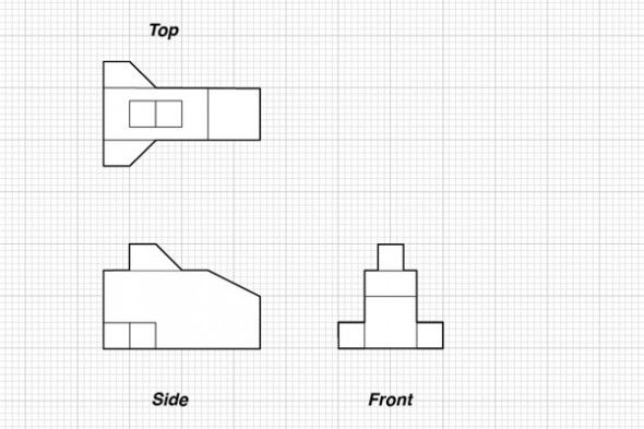
An orthographic is one way to describe a three dimensional object in two-dimensional space. Typically an orthographic will have the top, side and front views of an object drawn together with some kind of scale.
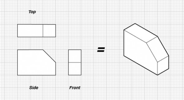
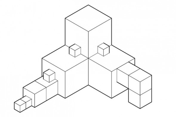
Top, front & side orthographics
An orthographic can have more then three sides drawn if the object has unique sides that would not be described clearly by just three images.
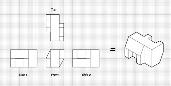
Top, front & 2-side orthographics
Once you have a clear set of orthographics you can draw your object in whatever method and from whatever view is required for your project. If you are planning to draw a set of orthographics from a physical object begin by measuring. Use a ruler and a set of calipers to measure all the surfaces of the object and make notes and a sketch. Once you are finished gathering data you can use your notes to create a set of orthographics in Illustrator. And that brings us to the world of isometrics.
Isometric projections are from the family of axonometric projection systems. Isometric comes from Greek for “equal measure”. This is because isometrics don’t use a vanishing point system, instead lines fall onto a 30° degree grid.
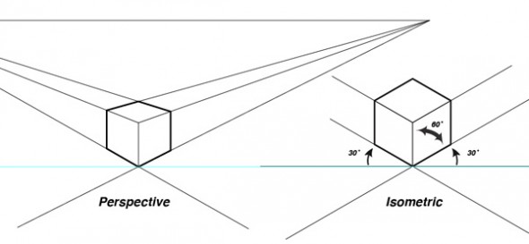
Perspective vs Isometric
Often the first impression of an isometric is that it looks “off”. This is more noticeable when an isometric cube is sitting next to a perspective cube. If you are going to be working in isometric there is a certain amount of distortion that comes with the territory. This is one of the factors that give isometrics their specific look. The huge upside to drawing in isometric especially using illustrator is that once you have created an object it will look exactly the same anywhere you place it. There are no vanishing points and no horizon lines. An object will be the same anywhere on your page. This is very important because you only ever have to drawn an object once. For example you could have an assembly drawing with one hundred screws in it. But you would only have to draw one screw and then copy it as many times as needed. This is a very powerful tool for speeding up workflow.
There are many other systems that don’t require vanishing points or horizon lines and give you similar benefits. But isometrics are the only one of these systems to make the jump from the technical illustrators toolbox to a useful skill for all graphic artists. The use of isometrics in early videogames has spawned a whole subculture of isometric pixel artists. And as the info-graphics style becomes very popular in magazines and newspapers you see isometrics being used more and more by artist with no technical illustration background.
Ok, now we can get into how to actually draw in isometric. The best way to start working in isometric is to make an isometric grid in Adobe Illustrator.
Step 1
Start by opening your preferences (Command K) and adjusting your keyboard increments to 1in.
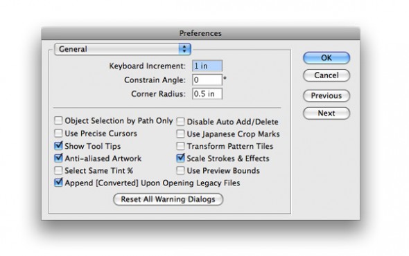
Illustrator's preferences panel
Step 2
Using your line tool option click somewhere on your page. A dialogue box will pop up. Make a 30in line on a 30° angle.
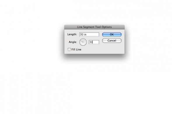
Illustrator's Line Segment Tool Options
Step 3
Move your line over to the left side of your page. Now while holding option tap the right arrow key once. Because we set the increments to 1in the line was copied 1 in to the left. Repeat until you have crossed the page.
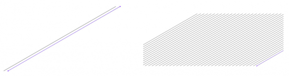
Creating an isometric grid
Step 4
You could repeat step 3 from right to left with a 1500 line. Or you can select all the lines and double click on the mirror tool and copy mirror horizontally.
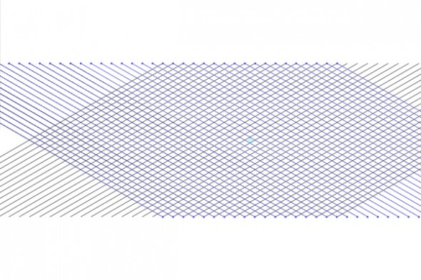
Creating an isometric grid
Step 5
Now you have an isometric grid. Select>All (command A) and hit (command 5) or View>Guides>Make Guides to turn your grid lines into guides. Save this file as iso grid template to use any time you want to work in isometric.

Isometric grid converted to guides
Step 6
Now we can start building objects on the isometric grid – first off a cube. Start by making a small 4 cornered shape with your pen tool.
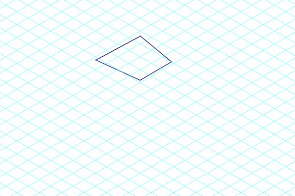
Drawing with the isometric grid
Step 7
Using your direct selection tool (white arrow) line up your 4 corners with a square on the grid.
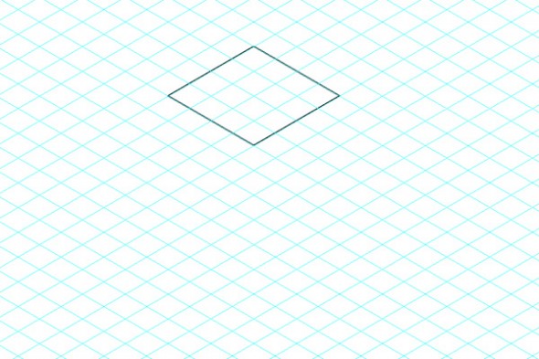
Drawing with the isometric grid
Step 8
Using your pen tool and the same method as above create the left and right sides of the cube. Quickly block out a four-cornered shape then move the corners into place with the direct selection tool. When building shapes on an isometric grid it is a good idea to start thinking of your objects in planes top, left side, right side. This will make more complicated objects easier to visualize.
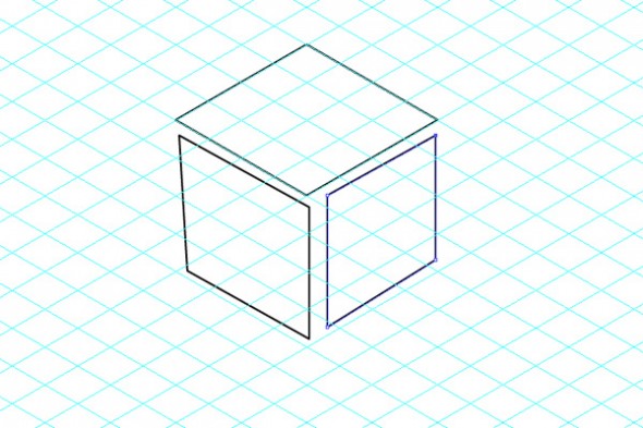
Drawing with the isometric grid
Drawing with the isometric grid
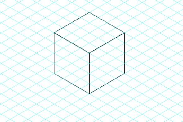
Step 9
Select all three parts and group (Command G). You now have an isometric cube. You can start making copies of the cube and quickly begin building larger shapes. You can scale the cube up or down and build with it.
Drawing with the isometric grid
Incorporating Orthographics
Now that you know the fundamentals of building a cube on an isometric grid we can incorporate the orthographics discussed earlier.
Step 1
Make a simple orthographic, with a scale that will work with your grid.
Simple orthographic plans
Step 2
Build the left side first. Using the pen tool rough out the shape by counting grid squares. Then line up the points with the direct selection tool.

Drawing in isometric from orthographic plans
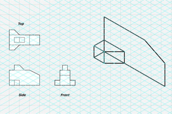
Drawing in isometric from orthographic plans
Step 3
Build the front of the shape. Count out grid squares, rough out the shape with the pen tool and clean up with the direct selection tool.

Drawing in isometric from orthographic plans

Drawing in isometric from orthographic plans
Step 4
Complete the top. By this point I’m sure you’ve come across parts of the shape that don’t just sit on their respective plane. This is where being able to actually read the orthographics and interpret them is essential. Or else you’ll just end up with a set of orthographics distorted onto three different planes.
Isometric vs. distorted orthographics
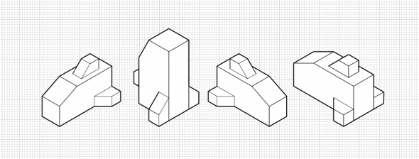
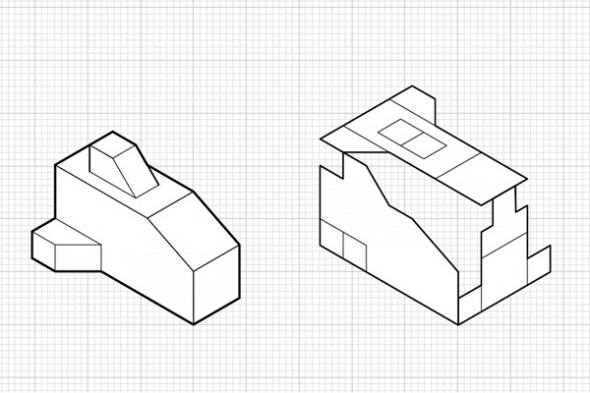
Step 5
Using the same orthographics draw the object from several different angles and orientations. Get very comfortable building basic shapes on an orthographic grid it will come in very useful once you start working on more complex objects.
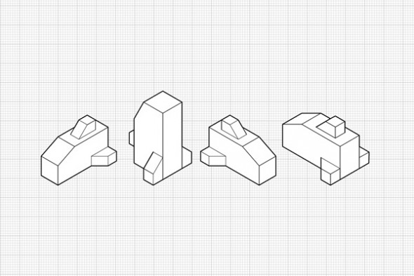
Different Isometric Views from the same Orthographic Plans
Good stuff! The one thing I always wished adobe illustrator had is a way of drawing in isometric like ISODRAW. That program was great for that 1 purpose. You could take a square or shape and project it onto a plane, put a hole through it and it would automatically thick and thin your lines. Usually when I draw in Iso I just turn on smart guides and adjust the angles.
wow you really believe in making things difficult for yourself don’t you!
The tut is much appreciated, but having done iso illustration for years, all you really need is to snap to the standard grid and observe that isometric is two blocks to one.
Also whats with using the pen tool to draw shapes then snap them to the guides? Surely it’s faster to just draw on the grid?
Also (sorry to go on) you didn’t reveal to the reader how you are making thin and thick lines. Sometimes this can be a very elaborate process of breaking objects up or cutting lines off their base shape.
Cody has more tutorials on the way that get into more advanced techniques.
Gotta walk before you run!
There are many ways to do iso illustrations and this is a good basic tutorial on one method. Honestly I’ve never considered adobe illustrator to be a very good program for creating isometric illustrations. I always created my iso’s in either autocad or isodraw and did the color and line work in illustrator. We could do an entire tutorial on thick and thin lines itself.
Nice, good information.
I use AI mostly for rendering.
The isometrics were generated within the CADD programs that supported our projects, ProE, AutoCAD, and Solidworks.
By learning to interface with these programs, one can save the time it takes to generate the isometrics = $.
BTW, AI has a set of ‘Actions’ that are preset to generate each of the 3 views of an orthographic projection to a respective isometric, Top, Front, Right side.
This will really help me in my Fiji Junior Examination. Thanks to This Website.
Coming in late to say that HotDoor CADTools makes this very, very easy.
For most recent news you have to pay a quick visit the web and on world-wide-web I
found this web page as a most excellent web page for most up-to-date updates.
It’s really a nice and helpful piece of info. I am satisfied that
you shared this helpful info with us. Please stay us
up to date like this. Thank you for sharing.
Thank you for your nice information. Though, I want to learn how to read and interpret these things. Since I am from Korea, we are obligated to learn how to read these isometrical projections. Please can you send me how to do this to my email?^^Thank you for your assistance~
Please send me soon~
Brian, the one grid is very busy and difficult to use so not to get mixed up. I prefer a stand type of grid either a 1 or 1/4 inch for each grid box. Much easier to keep straight.
3D Design is something that’s now more available to people.
wow
who wants t have sex with me!!!!!
Thank you for sharing these guidelines on orthographic projections and basic isometrics. The steps given are very important. The explanation given is very nice. I learned lot about orthographic projections from this tutorial.
This is a great tutorial on how to draw and produce orthographic lines. The step by step you did really helps me.